Adjust Sample Orthogonality
Check the sample scan for orthogonality along both the X- and Y-axes by scanning a square calibration grating. If the scan is aligned along
one axis of the scan but not another, it may be necessary to adjust the microscope’s Orthogonality
parameter in the Scanner Calibration panel.
Measure Orthogonality
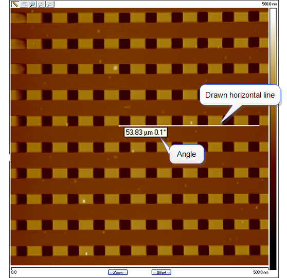
- To measure a captured image’s orthogonality, draw a horizontal line along a feature edge near the
image center. The software will display the length of the line (irrelevant to this measurement) and the angle from horizontal:
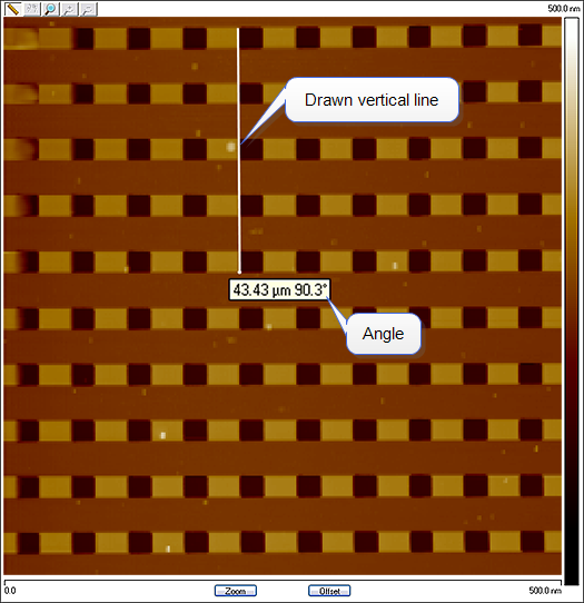
- Draw a vertical line along an edge near the image center. Again, the software will display the angle from horizontal:
- Perform the following calculation:
- Enter this value into Orthogonality in the Scanner Calibration dialog box.
- Click OK to exit the Scanner Calibration panel.
- Repeat correction of Orthogonality until the scanned image shows less than 0.5º of error.
NOTE: After a major change to the orthogonality parameter, you may need to
physically realign the calibration standard to the image frame.
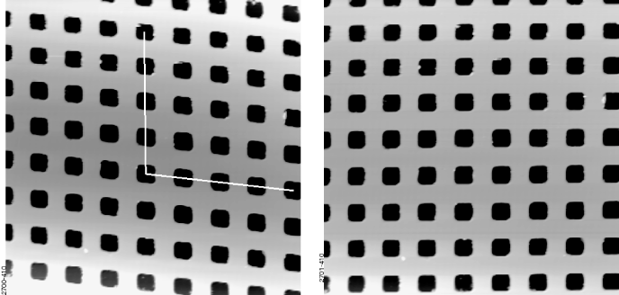
In the image above left, pits align with the vertical (slow) axis but skew with the
horizontal (fast) axis. The angle should be measured with the vertex near the
center of the image.
The image on the right is the orthogonality-corrected scan.
NOTE: Apparent orthogonality will change slightly between Trace and Retrace or
Up and Down scans due to the software displaying perfectly horizontal lines
while the scanner is actually moving at a slight angle during each scan line.
| www.bruker.com
|
Bruker Corporation |
| www.brukerafmprobes.com
|
112 Robin Hill Rd. |
| nanoscaleworld.bruker-axs.com/nanoscaleworld/
|
Santa Barbara, CA 93117 |
| |
|
| |
Customer Support: (800) 873-9750 |
| |
Copyright 2010, 2011. All Rights Reserved. |
Open topic with navigation